Light Sources
Light from source such as light bulb treated by considering each point
on surface.
Point (x,y,z)
Direction of emission (theta, phi)
Wavelength lambda
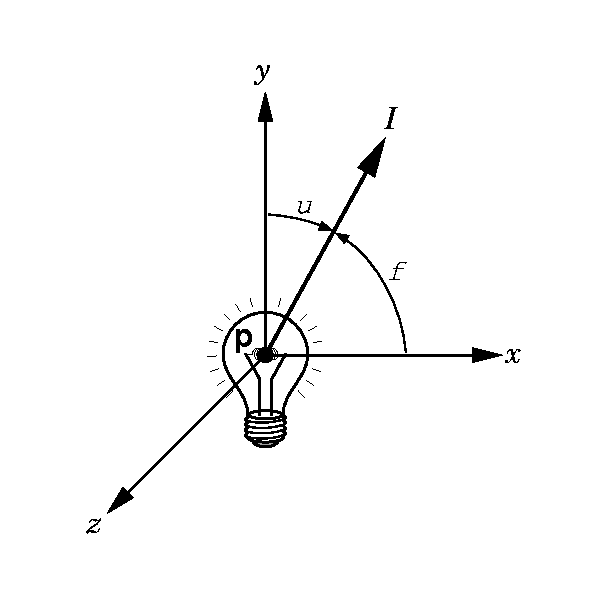
To get contribution from surface, integrate over surface - difficult
in practice.
Color
Treat each color independently. That is I = [ Ir, Ig, Ib]^T
Ambient Light
Considered uniform at each point in scence
Point Sources
Emits light equally in all directions. The light intensity
decreases with the square of the distance from the
source.
I(p, p0) = I(p0)/|p - p0|^2
where p0 is the source and p a point on a surface.
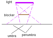
Problem with point sources. Object are either illuminated
or not - very sharp contrast.
In real life non-point sources give gradual shadows (umbra
and
penumbra)
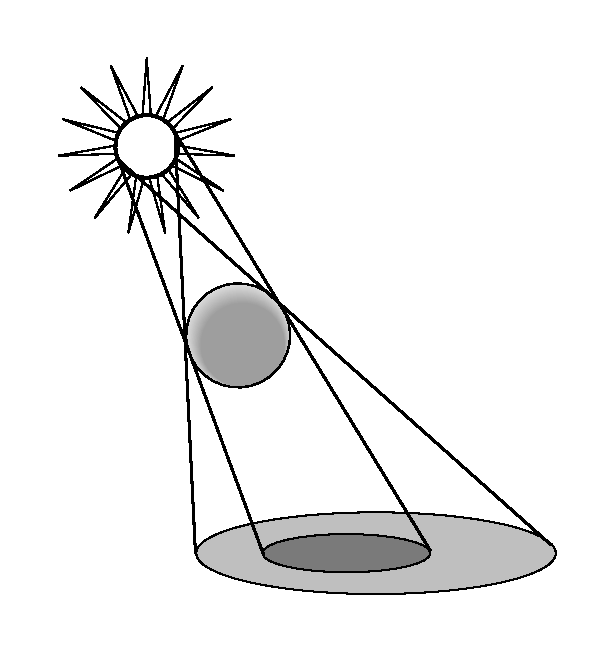
In OpenGL can soften contrast by using ambient light. Can also
do by using some other decay term than quadratic.
In OpenGL can use (a + bd + c d^2)^-1 where d is distance.
If source is sufficiently remote can assume light uniform over a surface.
Spotlights
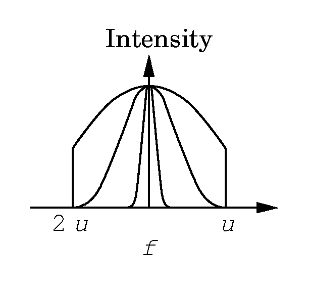
Point source - angle of light limited to theta - about direction Is. Theta
- 180 is point source.
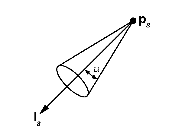
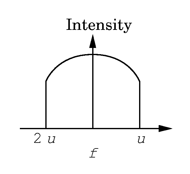
More realistic if light intensity falls off as w emove away from center
rather than just cut off at theta.
Modelled by intensity proportional to
Cos^e phi
where phi is angle away from Is.
Distant Light Sources
In the case of sources sufficiently far from surface we can assume that
light incident on each point
in the surface comes from the same direction. This avoids having to
calculate direction to source
seperately for each point.
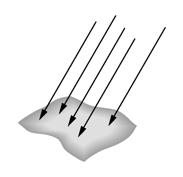
In practice replace location of light with direction of light. In homogeneous
coordinates this means replace
p0 = [x y z 1]^T with p0 = [x y z 0]^T.
Illumination Models
-
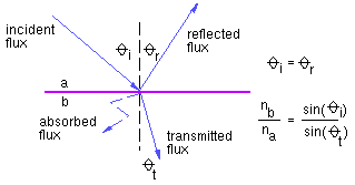
local illumination
-
defines single-light, single-surface interaction
-
global illumination
-
models interchange of lights between all surfaces
Local Illumination Models
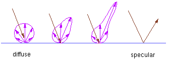
Traditional graphics LIMs are:
-
fast to compute
-
heuristic and incomplete (non-physical)
-
most interested in light in direction of viewpoint
Most such adhoc illumination models have three components:
I = ambient + diffuse + specular
Ambient Light
The ambient term allows for some global control of brightness in a scene.
Typically,
I = Ia ka
where Ia is an ambient illumination constant defined once for the
entire scene, and ka is an ambient reflection coefficient, usually
restricted to lie in [0,1].
Diffuse Reflection
-
Lambertian reflection
-
apparent surface brightness independent of viewing angle, since light reflected
equally in all directions
-
distribution of scattered light is independent of direction of arriving
light
-
amount of light illuminating surface DOES depend on angle of orientation
of surface relative to point source (direction of arriving light)
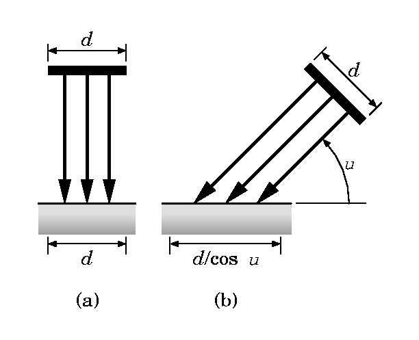
Id = Ii k_diff cos(th), th in [-pi/2, pi/2]
    = Ii k_diff (N.L),   N.L  0 and assuming N and L are normalized
Ii: intensity of light source i
k_diff: surface reflection coefficient
th: angle between N and L
Phong Specular Reflection
The last component of the commonly-used local illumination model is one
that takes into account specular reflections.
These are reflection from shiny surfaces which give rise to highlights.Note
that these are often a different color to the
reflected ambient and diffuse light.
For example a red ball viewed under white light is red because it reflects
the red component of the the ambient and diffuse
white light. However the specular reflection will cause a white highlight
in the direction of the viewer.
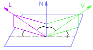
The following figure illustrates the situation:
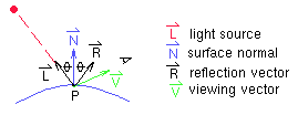
The Phong illumination model is one often-used method of calculating
the specular component:
  Is = Ii k_spec cos^n(alpha)
     = Ii K_spec (R.V)^n
where k_spec is a specular reflection coefficient and alpha is the angle
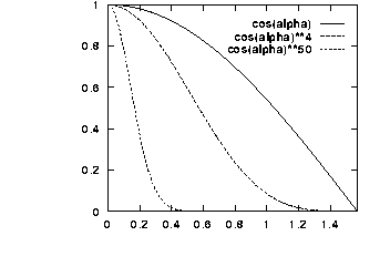
between the reflection and viewing vector. The surface parameter 'n' can
be thought of as describing the surface roughness, where an ideal mirror
would have n of infinity, and a rough surface might have n=1.
In OpenGL n is called the 'shininess'. Values of 100 to 500 correspond
to metallic surfaces showing narrow highlights, values < 100 to materials
showing broader highlights.
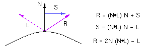
How can R be computed?
The function cos^n(alpha) looks as follows:
The Complete Model
Combining the various models and assuming the Phong illumination model
gives:
I = Ia ka + Ii k_diff (N.L) + Ii k_spec (R.V)^n
where each of ka, k_diff, and k_spec are parameters which are associated
with specific surfaces and take on values between 0 and 1. To deal with
colour, three equations of the above form are typically used:
I_r = Ia_r ka_r + Ii_r k_diff_r (N.L) + Ii_r k_spec_r (R.V)^n
I_g = Ia_g ka_g + Ii_g k_diff_g (N.L) + Ii_g k_spec_g (R.V)^n
I_b = Ia_b ka_b + Ii_b k_diff_b (N.L) + Ii_b k_spec_b (R.V)^n
Some other problems and their adhoc solutions:
-
What should be done if I>1?
-
Clamp the value of I to one.
-
What should be done if N.L < 0?
-
Clamp the value of I to zero or flip the normal.
-
How can we handle multiple light sources?
-
Sum the intensity of the individual contributions.
Distance effects
This is a more controversial issue. It is often considered that the light
from point sources attenuates as the square of the distance from the source.
Since point sources give unreasonably sharp shadows often add linear and
constant terms as well.
In OpenGL can use (a + bd + c d^2)^-1 where d is distance.
I = Ia ka + [ Ii k_diff (N.L) + Ii k_spec (R.V)^n ]/ (a + bd + c d^2)
Lighting in OpenGL
These are the steps required to add lighting to your scene.
Define normal
vectors for each vertex of all the objects. These normals determine the
orientation of the object relative to
the light sources.
Create, select,
and position one or more light sources.
Create and select
a lighting model, which defines the level of global ambient light and the
effective location of the
viewpoint (for
the purposes of lighting calculations).
Define material
properties for the objects in the scene.
Light Sources
The following are calls which set the parameters of a light (these are
the defaults for GL_LIGHT0)
GLfloat light_ambient[] = { 0.0, 0.0, 0.0, 1.0 };
GLfloat light_diffuse[] = { 1.0, 1.0, 1.0, 1.0 };
GLfloat light_specular[] = { 1.0, 1.0, 1.0, 1.0 };
GLfloat light_position[] = { 0.0, 0.0, 1.0, 0.0 };
glLightfv(GL_LIGHT0, GL_AMBIENT, light_ambient);
glLightfv(GL_LIGHT0, GL_DIFFUSE, light_diffuse);
glLightfv(GL_LIGHT0, GL_SPECULAR, light_specular);
glLightfv(GL_LIGHT0, GL_POSITION, light_position);
where light_position is (x,y,z,1.0) for positional light at x,y,z and
(x,y,z, 0.0) for a directional light from direction x,y,z
glEnable(GL_LIGHTING);
glEnable(GL_LIGHT0);
To specify attenuation use for example
glLightf(GL_LIGHT0, GL_CONSTANT_ATTENUATION, 2.0);
glLightf(GL_LIGHT0, GL_LINEAR_ATTENUATION, 1.0);
glLightf(GL_LIGHT0, GL_QUADRATIC_ATTENUATION, 0.5);
Note the default is constant attenuation.
For spotlights the added components are cutoff angle, direction, and
possibly the exponent
glLightf(GL_LIGHT0, GL_SPOT_CUTOFF, 45.0);
GLfloat spot_direction[] = { -1.0, -1.0, 0.0 };
glLightfv(GL_LIGHT0, GL_SPOT_DIRECTION, spot_direction);
glLightfv(GL_LIGHT0, GL_SPOT_EXPONENT, 5)
The larger the spot exponent the more concentrated the light.
Lighting Model
The OpenGL notion of a lighting model has three components:
The global ambient light intensity
GLfloat lmodel_ambient[] = { 0.2, 0.2, 0.2, 1.0 };
glLightModelfv(GL_LIGHT_MODEL_AMBIENT, lmodel_ambient);
Whether the viewpoint position is local to the scene or whether it should
be considered to be an infinite distance away
By default an infinite viewpoint is assumed. To specify a local viewpoint:
glLightModeli(GL_LIGHT_MODEL_LOCAL_VIEWER, GL_TRUE);
Whether lighting calculations should be performed differently for both
the front and back faces of objects
glLightModeli(GL_LIGHT_MODEL_TWO_SIDE, GL_TRUE);
Material Properties
The following calls define the surface properties to be used for all subsequently
drawn objects.
glMaterialfv( GL_FRONT, GL_AMBIENT, ambient_rgba );
glMaterialfv( GL_FRONT, GL_DIFFUSE, diffuse_rgba );
glMaterialfv( GL_FRONT, GL_SPECULAR, specular_rgba );
glMaterialfv( GL_FRONT, GL_SHININESS, n );
glMaterialfv(GL_FRONT, GL_EMISSION, emission_rgba);
-----------------------------------
More Complex Models
The Blinn Specular Model
Blinn reformulated the specular reflection model so that it agreed better
with experimental results. It makes use of a halfway vector, H, as follows:
Is = Ii k_spec cos^n(alpha)
     = Ii K_spec (N.H)^n
 The advantages of this model
include:
-
theoretical basis
-
N.H cannot be negative if N.L>0 and N.V>0
for a directional light and an orthographic projection, H is constant
Shading Algorithms
flat shading
Invoke illumination model (IM) once for the polygon, use this as a
colour for the whole polygon
Gouraud shading
Compute IM at the vertices, interpolate these colours across the polygon
Phong shading
Interpolate normals during scan conversion, apply IM at every pixel.
(note: renormalization problem)
Problems with shading algorithms
orientation dependence
silhouettes
perspective distortion
T-vertices
generation of vertex normals
Physics-based Illumination Models
BRDF: bidirectional reflectance distribution function

-
measuring BRDFs: gonioreflectometer
-
analytical models
-
statistical microfacet models
Shadows
-
projective rendering
-
draw object a second time with additional shadow transformation
-
darken existing image
-
use stencil buffer to prevent `double shadows'
-
raytracing
-
part of method
-
cast shadow ray
-
area light sources


 The advantages of this model
include:


