RENDERING TECHNIQUES FOR LINE DRAWINGS
In this section, we focus on a subgoal of realism: showing
3D depth relationships on a 2D
surface. This goal is served by the planar geometric projections defined
in Chapter 6
Multiple Orthographic Views
The easiest projections to create are parallel orthographics, such as plan
and elevation views, in which the projection
plane is perpendicular to a principal
axis. Since depth information is discarded, plan and
elevations are typically shown together, as with the top, front, side views
of a block letter "L" in Fig. 14.4. This particular drawing is not difficult
to understand; however, understanding drawings
of complicated manufactured parts from a set of such views may require
many hours of study. Training and experience sharpen one's interpretive
powers, of course, and familiarity with the types of objects being represented
hastens the formulation of a correct object
hypothesis. Still, scenes as complicated as that of our
"standard scene" shown in Color Plate 11.21 are often confusing when shown
in only three such projections. Although a single point may be unambiguously
located from three mutually perpendicular orthographics, multiple points
and lines may conceal one another when so projected.
In axonometric and oblique projections, a point's z coordinate influences
its x and
coordinates in the projection, as exemplified by Color Plate 11.22.
These projections
provide constant foreshortening, and therefore lack the convergence
of parallel lines and the
decreasing size of objects with increasing distance that perspective
projection provides.

Perspective Projections
In perspective projections, an object's size is scaled in inverse proportion
to its distance from the viewer. The perspective projection of a cube shown
in Fig. 14.5 reflects this scaling. There is still ambiguity, however;
the projection could just as well be a picture frame, or the parallel projection
of a truncated pyramid, or the perspective projection of a rectangular
parallelepiped with two equal faces. If one's object hypothesis is a truncated
pyramid, then the smaller square represents the face closer to the viewer;
if the object hypothesis is a cube or rectangular parallelepiped, then
the smaller square represents the face farther from the viewer.
Our interpretation of perspective projections is often based on the
assumption that a
smaller object is farther away. In Fig. 14,6, we would probably assume
that the larger house
is nearer to the viewer. However, the house that appears larger (a
mansion, perhaps) may
actually be more distant than the one that appears smaller (a cottage,
for example), at least
as long as there are no other cues, such as trees and windows. When
the viewer knows that
the projected objects have many parallel lines, perspective further
helps to convey depth,
because the parallel lines seem to converge at their vanishing points.
This convergence may
actually be a stronger depth cue than the effect of decreasing size.
Color Plate 11.23 shows a
perspective projection of our standard scene.
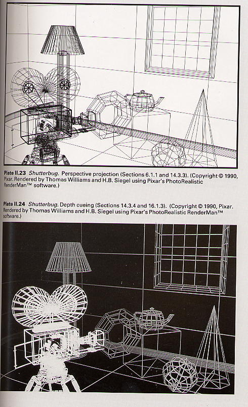
Depth Cueing
The depth (distance) of an object can be represented by the intensity of
the image: Parts of
objects that are intended to appear farther from the viewer are displayed
at lower intensity
(see Color Plate 11.24). This effect is known as depth cueing. Depth
cueing exploits the fact
that distant objects appear dimmer than closer objects, especially
if seen through haze.
Such effects can be sufficiently convincing that artists refer to the
use of changes in intensity
(as well as in texture, sharpness, and color) to depict distance as
aerial perspective. Thus,
depth cueing may be seen as a simplified version of the effects of
atmospheric attenuation.
In vector displays, depth cueing is implemented by interpolating the
intensity of the
beam along a vector as a function of its starting and ending z coordinates.
Color graphics
systems usually generalize the technique to support interpolating between
the color of a
(primitive and a user-specified depth-cue
color, which is typically the color
of the
background. To restrict the effect to a limited range of depths,
PHIGS+ allows the user to
specify front and back depth-cueing planes between which depth cueing
is to occur. A
separate scale factor associated with each plane indicates the proportions
of the original
Color and the depth-cue color to be used in front of the front plane
and behind the back
plane. The color of points between the planes is linearly interpolated
between these two
values. The eye's intensity resolution is lower than its spatial resolution,
so depth cueing is
not useful for accurately depicting small differences in distance.
It is quite effective,
however, in depicting large differences, or as an exaggerated cue in
depicting small ones.
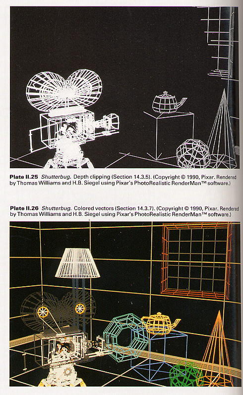
Depth Clipping
Further depth information can be provided by depth clipping. The back clipping
plane is
placed so as to cut through the objects being displayed, as shown in
Color Plate 11.25.
Partially clipped objects are then known by the viewer to be cut by
the clipping plane. A
front clipping plane may also be used. By allowing the position of
one or both planes to be
varied dynamically, the system can convey
more depth information to the viewer.
Back-plane depth clipping can be thought of as a special case of depth
cueing: In ordinary
depth cueing, intensity is a smooth function of z', in depth clipping,
it is a step function.
(Color Plate 11.25 combines both techniques. A technique related to
depth clipping is
(highlighting all points on the object intersected by some plane. This
technique is especially
effective when the slicing plane is shown moving through the object
dynamically, and has
even been used to help illustrate depth along a fourth dimension [BANC77].
Texture
Simple vector textures, such as cross-hatching, may be applied to
an object. These textures
follow the shape of an object and delineate it more clearly. Texturing
one of a set of
otherwise identical faces can clarify a potentially ambiguous projection.
Texturing is
specially useful in perspective projections, as it adds yet more lines
whose convergence
and foreshortening may provide useful depth cues.
Color
Color may be used symbolically to distinguish one object from another,
as in Color Plate
1.26, in which each object has been assigned a different color. Color
can also be used in
line drawings to provide other information. For example, the color
of each vector of an
object may be determined by interpolating colors that encode the temperatures
at the
vector's endpoints.
Visible-Line Determination
Tbe last line-drawing technique we mention is visible-line determination
or hidden-line
removal, which results in the display of only visible (i.e., unobscured)
lines or parts of lines. Only surfaces, bounded by edges (lines), can obscure
other lines. Thus, objects that
are to block others must be modeled either as collections of surfaces
or as solids.
Only surfaces, bounded by edges (lines) can obscure other lines. Thus,
objects that are to block others must be modelled either as collections
of surfaces or as solids.
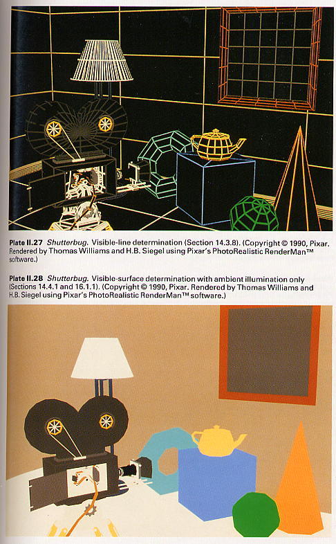
Color Plate 11.27 shows the usefulness of hidden-line removal. Because
hidden-lins-
removed views conceal all the internal structure of opaque objects,
they are not necessarily,
the most effective way to show depth relations. Hidden-line-removed
views convey less
depth information than do exploded and cutaway views. Showing hidden
lines as dashed
lines can be a useful compromise.
I
RENDERING TECHNIQUES FOR SHADED IMAGES
I
The techniques mentioned in Section 14.3 can be used to create line drawings
on both
vector and raster displays. The techniques introduced in this section
exploit the ability of
raster devices to display shaded areas. When pictures are rendered
for raster displays,.
problems are introduced by the relatively coarse grid of pixels on
which smooth contours
and shading must be reproduced. The simplest ways to render shaded
pictures fall prey to
the problem of aliasing, first encountered in Section 3.17. In Section
14.10, we introduce
the theory behind aliasing, and explain how to combat aliasing through
antialiasing.
Because of the fundamental role that antialiasing plays in producing
high-quality pictures,
all the pictures in this section have been created with antialiasing.
Visible-Surface Determination
By analogy to visible-line determination, visible-surface determination
or hidden-surface
removal, entails displaying only those parts of surfaces that are visible
to the viewer. As we
have seen, simple line drawings can often be understood without visible-line
determination.
When there are few lines, those in front may not seriously obstruct
our view of those behind
them. In raster graphics, on the other hand, if surfaces are rendered
as opaque areas, then
visible-surface determination is essential for the picture to make
sense. Color Plate 11.28
shows an example in which all faces of an object are painted the same
color.
Illumination and Shading
A problem with Color Plate 11.28 is that each object appears as a flat
silhouette. Our next
step toward achieving realism is to shade the visible surfaces. Ultimately,
each surface's
appearance should depend on the types of light sources illuminating
it, its properties (color,
texture, reflectance), and its position and orientation with respect
to the light sources,
viewer, and other surfaces.
In many real visual environments, a considerable amount of ambient
light impinges
from all directions. Ambient light is the easiest kind of light source
to model, because in a
simple lighting model it is assumed to produce constant illumination
on all surfaces,
regardless of their position or orientation. Using ambient light by
itself produces very
unrealistic images, however, since few real environments are illuminated
solely by uniform
ambient light. Color Plate 11.28 is an example of a picture shaded
this way.
A point source, whose rays emanate from a single point, can approximate
a small
incandescent bulb. A directional source, whose rays all come from the
same direction, can
be used to represent the distant sun by approximating it as an infinitely
distant point source.
Modeling these sources requires additional
work because their effect depends on the
surfaces orientation. If the surface is normal (perpendicular) to the
incident light rays, it is illuminated; the more oblique the surface is
to the light rays, the less its illumination. This variation in illumination
is, of course, a powerful cue to the 3D structure of an object. Finally,
a distributed or extended source, whose surface area emits light, such
as a bank of fluorescent lights, is even more complex to model, since its
light comes from neither a single direction nor a single point. Color
Plate 11.29 shows the effect of illuminating our scene with ambient and
point light sources, and shading each polygon seperately.
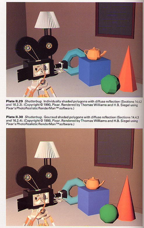
Interpolated Shading
Interpolated shading is a technique in which shading information is computed
for each
Polygon vertex and interpolated across the polygons to determine the
shading at each pixel.
This method is especially effective when a polygonal object description
is intended to approximate a curved surface. In this case, the shading
information computed at each vertex is based
on the surface's
actual orientation at that point and is used for all of the polygons that
share that vertex. Interpolating among these
values across a polygon approximates the smooth changes
in shade that occur across a curved, rather than planar, surface.
Even objects that are supposed to be polyhedral, rather than curved,
can benefit from
interpolated shading, since the shading information computed for each
vertex of a polygon differ, although typically much less dramatically
than for a curved object. When shading information is computed for
a true polyhedral object, the value determined for a polygon's vertex is
used only for that polygon and not for others that share the vertex. Color
Plate II.30 shows Gouraud shading, a kind of interpolated shading discussed
in Section 16.2.
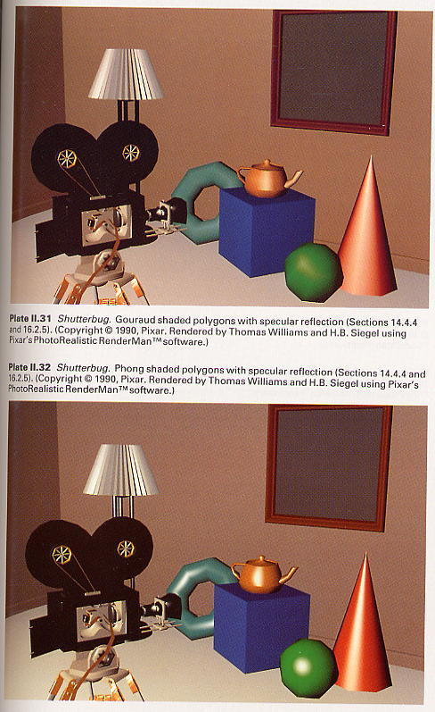
Material Properties
Realism is further enhanced if the material properties of each object are
taken into account when its shading is determined. Some materials
are dull and disperse reflected light about equally in all directions,
like a piece of chalk; others are shiny and reflect light only in certain
directions relative to the viewer and light source, like a mirror. Color
Plate 11.31 shows what our scene looks like when some objects are modeled
as shiny. Color Plate 11.32 Phong shading, a more accurate interpolated
shading method (Section 16.2).
Modeling Curved Surfaces
Although interpolated shading vastly improves the appearance of an image,
the object
geometry is still polygonal. Color Plate
11.33 uses object models that include
curved surfaces. Full shading information is computed at each pixel in
the image.
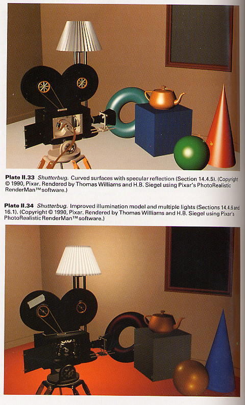
Improved Illumination and Shading
One of the most important reasons for the "unreal" appearance of most computer
graphics
images is the failure to model accurately the
many ways that light interacts with objects.
Color Plate 11.34 uses better illumination models. Sections 16.7-13
discuss progress tovn
the design of efficient, physically correct illumination models, resulting
in pictures such
Color Plates 111.19-111.29 and the jacket of this book (Color Plate
1.9). ;
Texture
Object texture not only provides additional depth cues, as discussed in
Section 14.3.6,!
also can mimic the surface detail of real objects. Color Plates II.
35 and II. 36 show a variety
of ways in which texture may be simulated, ranging from varying the
surface's color (as is
done with the patterned ball), to actually deforming the surface geometry
(as was done with
the striated torus and crumpled cone in Color Plate 11.36).
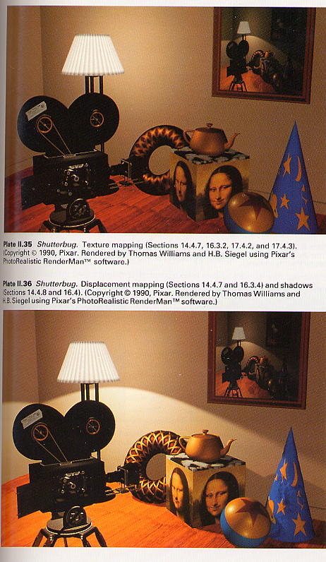
Shadows
We can introduce further realism by reproducing shadows cast by objects
on one anoti
Note that this technique is the first we have met in which the appearance
of an obja
visible surfaces is affected by other objects. Color Plate 11.36 shows
the shadows cast by
lamp at the rear of the scene. Shadows enhance realism and provide
additional depth ci
If object A casts a shadow on surface B, then we know that A is between
B and a direci
reflected light source. A point light source casts sharp shadows, because
from any point i
either totally visible or invisible. An extended light source casts
"soft" shadows, si
there is a smooth transition from those points that see all of the
light source, through th
that see only part of it, to those that see none of it.
Transparency and Reflection
Thus far, we have dealt with opaque surfaces only. Transparent surfaces
can also be us<
in picture making. Simple models of transparency do not include the
refraction (bendi
of light through a transparent solid. Lack of refraction can be a decided
advantage, hovw
if transparency is being used not so much to simulate reality as to
reveal an object's in
geometry. More complex models include refraction, diffuse translucency,
and
attenuation of light with distance. Similarly, a model of light reflection
may simulate
sharp reflections of a perfect mirror reflecting another object or
the diffuse reflections i
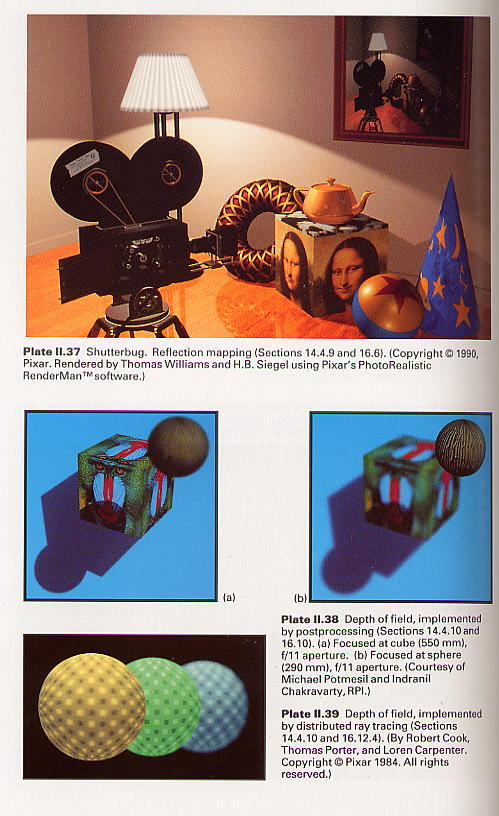
less highly polished surface. Color Plate 11.37 shows the effect of
reflection from the floor
and teapot; Color Plates 111.7 and 111.10 show transparency.
Like modeling shadows, modeling transparency or reflection requires
knowledge
other surfaces besides the surface being shaded. Furthermore, refractive
transparency is
first effect we have mentioned that requires objects actually to be
modeled as solids ral
than just as surfaces! We must know something about the materials through
which ali
ray passes and the distance it travels to model its refraction properly.