| UNIVERSITY of VIRGINIA Computer Science | ||||||||
| Research | Teaching | People | Community | |||||
Search
Directory
Contact Us

| Search Directory Contact Us | | ||||||||||||||||||||
| Of interest to: Prospective Students, Members | ||||||||||||||||||||||
The University of Virginia's Computer Museum was conceived and created by Professor Gabriel Robins, who also serves as its curator.
The museum contains various computer-related artifacts, both historical and modern. Most of the artifacts shown here are physically located in display cases in the hallways of the Department of Computer Science (Olsson Hall) at the University of Virginia.
These artifacts came from the personal collections of some of our faculty members, and several other donors, including Professor Sam Cooke of the University of Louisville. To see an enlarged view of any or the artifacts / photos, please click on it.
The descriptive captions accompanying the photos are correct to the best of our knowledge. Please report any mistakes or discrepancies to webteam@cs.virginia.edu.
Enjoy!
 UVa's first computer - a Burroughs B205 (1960). |
The Burroughs 205: |
The Burroughs B5000:
|
 UVa's Burroughs B5000/5500 (1964-1973). |
The IBM 704: |
 A tradeshow button: the B5000 was an extremely unconventional and exotic machine - as Brian Randell said - "the machine that everyone loves, and nobody buys". |
 A single digit from the accumulator of a Burroughs 205, circa 1954. The 205 was a decimal macine with a magnetic drum for primary memory. |

|

|
| Modules from the Burroughs B5000 computer - early 1960s. This "ruggedized" construction was a spin-off from military spec. machines. Burroughs B5000 modules plugged into a section of the backplane. | |
| The register display panel of a B5000. This was the first machine to have its displays "hidden" from the casual viewer - machines prior to this delighted in displaying the flashing lights! |

|

|

|
| Burroughs Corp. printed circuit boards. Note the extremely large area contacts at the right. | |
 Power triode. Similar in size to power tubes used on the early computers, but this particular tube type is brand-new. It can be compared with a power transistor of comparable power rating. |
 Photomultiplier tube, used to measure light intensity. It was not directly used in computers, but rather in instrumentation which may be connected to computers. |
 An assortment of 9-pin vacuum tubes and circuit modules. |
 Numitron display tube on a circuit board. The Numitron tube consists of 7 wire segments which can be illuminated in any combination to form numerals, much like more modern liquid crystal displays (LCDs). |

| Vacuum tube based counter. Four dual triodes are used to count and store the 4 bits needed to represent a decimal digit. Each tube has two triodes (visible through the glass envelope). The pair of triodes form a flip-flop which can have either of the triodes in a set (i.e. 1) state, with the other triode in a cleared (i.e. 0) state. |

| A "core" memory plane. The magnetic orientation of an individual memory core can be changed by passing current through a wire in the center. Storage and retrieval is based on the fact that half the current required to set (or clear) the magnetic field has no effect. With half the current sent along a wire from one direction (X) and half the current along a wire coming from an orthogonal direction, only the core at the junction (i.e., the intersction of the two wires) will be influenced. |
 A "gift" from IBM; it is a piece of plastic with a discrete transistor and three magnetic "cores" embedded in it. It is typical of early 1960's technology. |
 A core memory plane from a CDC 6600, a computer designed by Seymour Cray in the 60's, before he started his own company, and the earliest successful "supercomputer". |
 Core memory module made for the George C. Marshall Space Flight Center by Electronic Memories Inc., with a memory capacity of 38 x 100 bits. This was probably a special design, bearing the serial number 2. |

| DEC logic trainer input/output panel. The 8 switches and 8 lamp indicators provided user interface for the logic modules inserted into other panels. DEC originally manufactured larger logic modules and built these units to use the newer printed circuit modules. |
| DEC logic trainer patch panel. The logic or regular computer modules were inserted into sockets on the back of this panel. The individual logic signals were interconnected by the user on the front panel, aided by diagrams inserted at the proper place on the front panel. |

|
 One of the original DEC "flip chip" modules. Before they began making computers, DEC made these modules which could be wired together to build special-purpose laboratory instrument controllers. |
 An early DEC module - this one is labeled an "integrating one shot". |

| Program spindle for IBM 026 or 029 card punch. For repeated data entry with a fixed card format, the card punch could be set up to skip certain columns, wait for key input, or duplicate information from the previous card. Program cards were punched on the same keypunch, removed, wrapped around the drum, and inserted in the keypunch above the punch position. Control by the card could be enabled and disabled by the operator with a lever. |
| Punch card chad - a jar of 'holes' punched from cards on an IBM '029' punch. These are rectangular in shape, have the color of the card, and usually bear the small printed column number that was punched out from the card. |

|

| Manual card punch from Wright Line. Numeric digits could be inserted directly from the keys. Alphabetic and special characters required 2 or 3 holes obtained by pressing all needed keys while holding down the 'S' key at bottom until finished. For example an A (shown in the table to the left of the keys) required both a '12' and a '1' punch. |

|

|

|
|
Fan-folded paper tape for a DEC PDP-9 optical reader, circa 1968.
The software for this computer was distributed and used in this format.
The reader operated at 300 characters per second. The '8 level' tape has
an additional smaller 9th hole to engage a drive gear. The system software
shown here includes a FORTRAN IV compiler, and a MACRO-9 Assembler.
Fan folded paper tape for PDP-9 in plastic case and protective
clear plastic envelope. The process of creating and executing a Fortran
program required these steps starting from 'power-on':
| |

|
| Repair tape for 8-level paper tape. When a paper tape is damaged or cut, repairs can be made using this pre-punched adhesive tape. The damaged tape is straightened out and the repair tape moistened and placed over it. Holes which existed before the damage will thus still be clear. |

| A "DEC tape" - a magnetic tape used on several early DEC computers. It was notable in that it was "addressable" - one could move forward or backward to a specified tape block. This particular tape contains the source code for the first Pascal Compiler, written by the inventor of Pascal, Nicklaus Wirth. |
 9-track magnetic tape, certified at 6250 bits/inch. This tape is in a housing for automatic loading on the tape drive. |
 Magnetic tape cartridge (for back up). |

| A cartridge from a 1960-era tertiary memory device built by IBM. The cartridge contains about a thousand 2"x12" strips of magnetic material (i.e., short, fat tapes) that have encoded notches on one end. A mechanical device would select a strip from the cartridge and wrap it around a spinning drum for reading or writing. Tens or hundreds of these cartridges were in a single device. |
| Hard disk platter. This was a popular means of storing large quantities of information on early larger computers ('mainframes'). |

|

| Helios 8" floppy drive for a SOL microcomputer. An option for the SOL computer, this dual floppy drive weighed over 40 Pounds. |
| Eight-inch floppy disk cut open to show actual disk material. The hole in the envelope is for a light beam to identify when a particular reference point on the disk is passing the read/write head. |

|

| Top/side view of the original IBM full height 5 1/4" disk drive, showing door mechanism to lower heads gently as they approach each other when closed, and the 'in use' red LED on front. |
| Bottom view of a full height 5 1/4" disk drive. The belt drive mechanism is shown along with stroboscopic timing patterns for both 50 and 60 hertz lighting. The motor in the lower left positions the read/write heads to the desired track. |

|
 Control logic of a 1980 era 20 megabyte hard disk. |
 Eight-inch floppy disk for the SOL containing CP/M from Digital Research (1978), the dominant operating system for most of the early microcomputers. |

|
| Acoustic coupler - a 10 characters/second "modem". In use, the telephone handset was place in the rubber cups. Communication was established through audio tones with no electrical connection between computer and telephone line. Such connections were generally limited to <300 bits per second and were often favored since prior approval of the carrier was (assumed) not necessary. |

| Qubie 100-baud modem board (PC bus). |
| A 110/300 bits/second Hayes Modem (S-100 bus) circa 1978. |

|

| Anadex printer drum. This very massive cylinder contains the entire character set wrapped around the cylinder and repeated 80 times along the length of the cylinder. The mass and ball bearings facilitated maintenance of a constant angular velocity. When the character needed in a given position was (more or less!) in line, a solenoid hammer pressed the paper from behind against an ink ribbon and the print drum. This was a 'line printer' rather than the more common character printer of the day. |
| The write head from a modern "label-writer" - a small special purpose thermal printer designed to make labels for envelopes. |

|
 A circuit board from a Dutch computer on which Edgsar Dijkstra implemented a famous operating system called THE in the 1960's. |
 A printed circuit board from "crossbar switch" or C.mmp -- an experimental multiprocessor built by Bill Wulf 's group at Carnegie Mellon University in the 1970's. Cimmp had 16 PDP-11 processors. |
| The module for a CDC 160 computer. This small peripheral computer was used to control the input and output magnetic tape preparation for the CDC 1604 - the first high performance commercial machine to use transistors. |

|
 A CDC 6600 logic board.
|

| A "gift" from Cray Computer Inc., containing contains three GaAS chips that were to be part of the Cray 3 computer (before Cray Computer went bankrupt). The large brownish item in the center is a miniature "printed circuit board" -- the idea was to bind the chips directly to this board (rather than to first package them in individual carriers) -- this allowed smaller, denser packaging. |
| A "multi chip module", that is a number of chips bonded directly to a substrate that serves the same function as a "printed circuit board", but fabricated with the same technology as is used to make the chips themselves. In this case the MCM is serving the function of a "motherboard" for a complete SPARC. |

|
 Intel 432 processor chips -- the machine was very complex, but ultimately did not perform well. Nonetheless, the chip itself was interesting for being one of the largest of its time. |
 An IBM-Motorola-Apple Power PC chip
|
 A circuit board from the Stream Memory Controller Project here at UVa. |
 The design layout for a mixed analog/digital device to measure corrosion rates. The big colored areas are operational amplifiers. |

| An 8-inch wafer containing about one-hundred-and-sixty 8080 microprocessor chips. The wafer is then "sliced" into individual chips which are then packaged individualy |
| An NCUBE-2 CPU board, containing 64 1-MIP processors, each with 512K of memory. The NCUBE was one of three early hypercube -connected distributed memory MIMD machines (the others being the Intel IPSC/2 and the CalTech Cosmic Cube). NCUBE-2 systems with up to 512 nodes were constructed. The board shown here is from the 128-node machine used at UVa in the late 1980's. |

|

| Northstar 16K memory card (S-100 bus), circa 1980. Contains 4 x 9 chips indicating the parity bit was included. Parameters are set with switches in DIP (Dual Inline Plastic) sockets at the upper right and with blue jumpers found to the right of the center of the board. |
| IMS Associates memory (PROM) board with 'self-contained system'. The contents of this memory were available on 'power-up' and thus enabled a much more rapid boot up process. The address is entered by jumpers on a plug located on the bottom row of chips. |

|

| AST SixPak circuit board. Multifunctional board with serial, parallel, memory expansion, clock, and calendar. Only one set (9 chips) of memory expansion chips are installed. |
| An S-100 Maintenance board (Mullen, 1976). This board was used to allow operation of the computer with one of the circuit boards elevated above the others for testing. A jack for a logic probe was built into the board at the upper right just below the LED indicators. |

|

| The Digital Equipment Corporation Rainbow mother board was most notable for having dual processors: the 8088 (long IC left of the larger label), and the Z-80 (5 chips above the 8088). The Rainbow had a peculiar dual disk drive design: it had two drives arranged vertically about one drive motor (which required insertion of the upper disk with its label down); special disks were required (originally only available pre-formatted from DEC since no format program was provided). |

|

|
| Northstar disk controller card (left) and Z-80 processor board (right) (S-100 bus). | |
| Circuit module: the tube socket at the top is connected to components in the middle and connectors at the bottom to form a compact plug-in module. |

|

Multitrack tape recorder heads. |

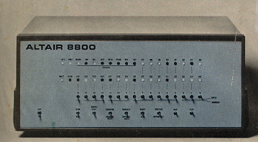
| The Altair 8800, an early personal computer, distributed in kit form. Programs were entered by using the switches on the front of the unit, and output was returned via a binary LED readout. Click the image to access the Popular Electronics article announcing the 8800's release. |
| MITS-Altair memory PROM board (S-100 bus). This board was purchased in the early days of the Altair (1975) and was sent back to MITS for repairs. Some of the extensive add-on wiring may have been installed at that time to correct design problems. The base address is wired with jumpers in the area below and to the right of the larger label which shows the test results at MITS. |

|

| MITS-Altair memory board (S-100 bus), circa 1975. |
| MITS-Altair memory board (S-100 bus), circa 1975. |

|

| MITS-Altair 88-VI (I/O) board (S-100 bus), circa 1975. |
| Godbout 4K Memory board for the MITS-Altair (S-100 bus), circa 1975. Contains 4x8 or 32 memory chips each holding 1 K bits (no parity). The five larger black objects at the extreme left are onboard voltage regulators. The base address of the board is set by the hardwire connections seen at the bottom right of the board. |

|
| SOL computer/keyboard console, by Processor Technology Corp. A monochrome TV set was used for a monitor. This particular unit had only one crash which proved to be the 8080 chip - one of the less expensive parts. |

|

|
|
| The Osborne portable computer, open and ready for use. The screen unit fits into slots on the keyboard unit. The 5" diagonal screen (that's 3 x 4 inches!) displayed some 60 print columns and the software allowed left-right shifts to see the entire 80 column line. This model had dual floppy drives, and an 'internal' modem in the left hand disk storage slot. The modem is connected by a short jumper cable to the cabinet and has a conventional modular RJ-11 telephone plug. The socket on the right could provide (with an adapter) an NTSC or standard TV monochrome signal to drive a (larger!) external TV monitor. A serial port connector is found at the extreme right, and a printer connection is located to the right of the modem connector. | |

|
| Osborne Computer software disks that were distributed with the Osborne hardware. The Osborne computer was marketed with a bundle of software which included CBASIC and MBASIC, WordStar and MailMerge, and dBase II. Since each computer manufacturer used a proprietary disk format, it was necessary to buy software specifically for the particular brand (and sometimes the model) of microcomputer. |
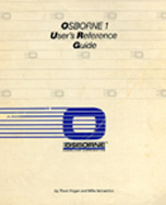
| Manual accompanying computer software for the Osborne computer. |

|
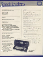
| A specifications sheet for the Osborne 1 computer. This early entry into the area of 'portable' computing weighed in at a spritely 26.2 pounds, and was powered by the popular Z80A processor, running at 4MHz. For comparison, a variant of the Z80 is currently used in many graphing calculators. |

| A Compaq I, first IBM clone said to be ">99% compatible". The owner found only one incompatibily in four years of use and that involved the use of graphics from within a BASIC program. |
| Analog to Digital converter board for Apple II. The analog data is converted into a BCD or Binary Coded Decimal value in which each decimal digit is represented by 4 bits. Although less efficent storage than pure binary, BCD is easily obtained (at slower data acquisition rates) using circuitry developed for manual use. |

|

| Mountain Computer A/D and D/A board for Apple II, which converts analog (voltage) signals into digital form which can be processed by the Apple II. Can also convert computer generated data (digital) into analog (voltage) form. The upper left corner is beveled to fit below the sloping cabinet of the Apple II. |
| Calendar clock module for Apple II. Includes a battery to maintain the time when power is off. |

|

|

|

|

|
| Boards from a special purpose color matching computer named COMIC II and made by Davidson & Hemmendinger. The word COMIC is from "colorant mixture". The COMIC machine was used by colorist to predict the color that would result from mixing individual colorants. [Thanks to Hugh Fairman for providing this information.] | |
| VPL Eyephones. The first commercially available head-mounted display for use in virtual reality applications. One of the internal displays and optics-sets has been removed. |

|
 Tier-1 Head-mounted Display. |
 Special-purpose slide rule for transformer calculations. |
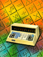
 Early scientific calculator by Commodore. |
 Catalog of Wang Scientific Calculators, circa 1968-69. |
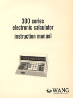 Instruction manual for the Wang 300 series caculators. |

|
Early scientific calculators were programmed in the same way as many early computers, through the use of punch cards. This punch card program for a Wang 300 Series calculator implements the Pythagorean Theorem. |
 A 1950's-era electromechanical telephone switching element
|
 Telephone relay control board, built by Western Electric. |
| | ||
 | Department of Computer Science School of Engineering, University of Virginia 151 Engineer's Way, P.O. Box 400740 Charlottesville, Virginia 22904-4740 (434) 982-2200 Fax: (434) 982-2214 | Web Comments: webteam@cs.virginia.edu Admissions Inquiries: inquiry@cs.virginia.edu Site directory, Other addresses Server statistics © Created by the CS Web Team |
