Non-Rigid Registration
Thin-Plate Spline
1. Background
Thin-plate spline comes from the physics concept. It is used for the non-rigid
registration, because they have the property of minimizing the "bending" energy.
The idea is best thought of as a two dimensional deformable plate
(such as a thin steel plate) where you are pushing up from underneath it
at a given set of points. Because you are requiring the height of
the plate to be fixed at given locations, the plate will bend to fit. The
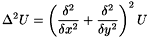
energy required to do the bending can be parameterized as satisfying the
biharmonic equation:
The solution to this equation takes the form: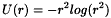 where
where  is the Euclidian distance.
This however, represents a z-axis displacement to the deformable plate.
When you are deforming images, what you actually want to do is an
in-plane deformation. You want to move an (x, y) location to a new
(x', y') location. This is very easy to do, as you simply create an
function for the x displacement, and a function for the y displacement.
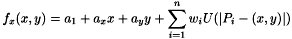
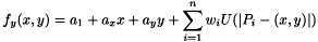
Where represents  represents the ith landmark point. And the distance
is calculated using the Euclidian distance
represents the ith landmark point. And the distance
is calculated using the Euclidian distance 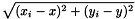
The nice thing about this form for .png) is that it can easily be rewritten into a matrix form:
is that it can easily be rewritten into a matrix form:
_matrix.png)
The only thing left is to compute the weights for W_I, and A_I. This
is done by creating a list of the deformations at each of the landmark points.
In other words, you write down the equation
for each landmark point,
. Then you solve the system of equations by doing a matrix inversion.
2. Coding:
IDL is the environment used here.
In nonrigid.pro the TPS is calculated. Then the
formula is used to calculate the corresponding position of all the
points in the template image.
3. Result:
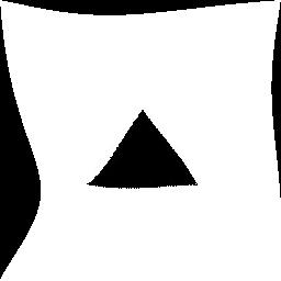
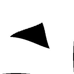
One Simple example
 |
 |
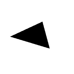
| Template |
Target |
The Control points will be selected as the vertex of the triangle
 |
 |
 |
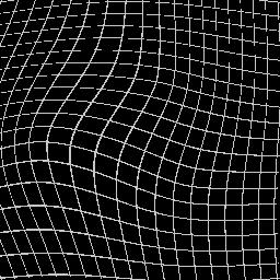
| Deformed Template |
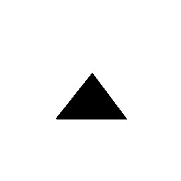
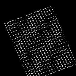
Template Grid |
Deformed Template Grid |
 |
|
 |
| Deformed Target |
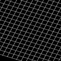
Target Grid |
Deformed Target Grid |
If the control points in these two images include in the four corner of
the image:
 |
|
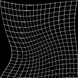 |
| Deformed Template |
Template Grid |
Deformed template grid |
 |
|
 |
| Deformed Target |
Target Grid |
Deformed target grid |
The clips generated to demonstrate the deforming procedure:
(1) 3 Control points
(2) 7 Control points
Following is the template image and target image which are more complex.
(1) Control Points including the four corners.
(2) Control Points not include the four corners.
(3) More Control Points including the four corners.
12/12/2002