This is useful to evaluate long strings of 1-bits. For example: 0111 1111 1111 0000 has the value 215 - 24 = 32768 - 16 = 32752.
The MIPS computer performs integer arithmetic in its 32-bit registers. The modulus is M = 232 = 4,294,967,296 and signed integers are represented as follows:
| binary bits | decimal integer |
|---|---|
| 0000 0000 0000 0000 0000 0000 0000 0000 | 0 |
| 0000 0000 0000 0000 0000 0000 0000 0001 | 1 |
| 0000 0000 0000 0000 0000 0000 0000 0010 | 2 |
| 0000 0000 0000 0000 0000 0000 0000 0011 | 3 |
| . . . | . . . |
| 0111 1111 1111 1111 1111 1111 1111 1101 | 2,147,483,645 |
| 0111 1111 1111 1111 1111 1111 1111 1110 | 2,147,483,646 |
| 0111 1111 1111 1111 1111 1111 1111 1111 | 2,147,483,647 |
| 1000 0000 0000 0000 0000 0000 0000 0000 | -2,147,483,648 |
| 1000 0000 0000 0000 0000 0000 0000 0001 | -2,147,483,647 |
| 1000 0000 0000 0000 0000 0000 0000 0010 | -2,147,483,646 |
| 1000 0000 0000 0000 0000 0000 0000 0011 | -2,147,483,645 |
| . . . | . . . |
| 1111 1111 1111 1111 1111 1111 1111 1101 | -3 |
| 1111 1111 1111 1111 1111 1111 1111 1110 | -2 |
| 1111 1111 1111 1111 1111 1111 1111 1111 | -1 |
The left-most bit is the sign bit with a weight of -231 = -2,147,483,648. The weight of every other bit is positive.
| -2,147,483,648 | 1,073,741,824 | 536,870,912 | . . . | 128 | 64 | 32 | 16 | 8 | 4 | 2 | 1 |
|---|
The MIPS computer extends 16-bit two's complement signed integers to 32 bits by sign extension: the bits of the short integer are copied into the right-most part of the long register and its sign bit is copied repeatedly into the left-most part of the long register.
What is the negative of a signed integer in two's complement form? Complement each bit (change 0 to 1 and 1 to 0) and then add unity.
A register may contain a signed integer in two's complement form or it may contain a memory address which is always non-negative. This affects how comparisons are performed. For example, 1111 1111 1111 1111 1111 1111 1111 1111 has the value of -1 if it represents a signed integer or the value +4,294,967,295 if it is a memory address. To handle this problem the MIPS instruction set contains both signed (slt and slti) and unsigned (sltu and sltiu) comparison instructions.
3.3 - Addition and Subtraction
Addition of binary numbers is similar to paper-and-pencil addition of decimal numbers: start at the right-most column and work toward the left adding the digits in each column and passing any carries into the next column. For binary numbers the only digits are 0 and 1 and a carry is created whenever the sum is two or more. For example, the addition of 0000 0000 0110 1100 and 0000 0000 0101 1010 looks like:
0 0 0 0 0 0 0 0 0 1 1 0 1 1 0 0   (augend)
0 0 0 0 0 0 0 0 0 1 0 1 1 0 1 0   (addend)
                1 1 1 1           (carries)
-------------------------------
0 0 0 0 0 0 0 0 1 1 0 0 0 1 1 0   (sum)
The addition in decimal is 108 + 90 = 198.
Subtraction is performed by adding the negative of the subtrahend (in two's complement form) to the minuend to get the difference. As an example 0000 0000 0101 1010 is subtracted from 0000 0000 0110 1100. First, the subtrahend (0000 0000 0101 1010) is negated by complementing each bit (1111 1111 1010 0101) and adding unity to obtain 1111 1111 1010 0110. Then the negated subtrahend is added to the minuend:
    0 0 0 0 0 0 0 0 0 1 1 0 1 1 0 0   (minuend)
    1 1 1 1 1 1 1 1 1 0 1 0 0 1 1 0   (negated subtrahend)
(1) 1 1 1 1 1 1 1 1 1 1   1 1         (carries)
    -------------------------------
    0 0 0 0 0 0 0 0 0 0 0 1 0 0 1 0   (difference)
This example assumes registers are only 16 bits long so the carry
out of the left-most column (shown in parentheses) was neglected.
The subtraction in decimal is 108 - 90 = 18.
Overflow Detection: Integer addition (subtraction) overflows when the magnitude of the sum (difference) is too large to be stored in the result register. In the MIPS computer the length of each register is 32 bits so addition (subtraction) is performed with a modulus, M = 232 = 4,294,967,296. If overflow occurs the value stored in the result register has an error of +M or -M.
In 32-bit two's complement arithmetic, a number with a 0 sign bit is in the range of 0 through 231-1 and a number with a 1 sign bit is in the range of -231 through -1. Using these facts plus the fact that overflow commits an error of +M or -M, one can derive the following rules for detecting when overflow occurs:
- Addition overflow occurred if and only if the sign bits of the
augend and the addend agree but the sign bit of the result disagrees.
- Subtraction overflow occurred if and only if the sign bits of the subtrahend and the result agree but the sign bit of the minuend disagrees.
The MIPS computer has two sets of instructions for integer addition and subtraction: instructions in one set detect overflow on signed integer operations and instructions in the other set don't detect overflows.
The add, add immediate, and subtract instructions (add, addi, sub) assume signed integers are being treated and cause an exception if any result overflows.
The add unsigned, add immediate unsigned, and subtract unsigned instructions (addu, addiu, subu) do not cause exceptions on overflow.
3.4 - Multiplication
As an example we use the paper-and-pencil method to multiply decimal 396 by decimal 302:
    396
x   302
 ------
    792  <-- 2 * 396
   000   <-- 0 * 396
 1188    <-- 3 * 396
 ------
 119592
The multiplier digits are treated one at a time starting at the right
and going to the left. The multiplicand (396) is multiplied by each
multiplier digit and the products added together with appropriate
shifts to get the final product (119592).
Binary numbers can be multiplied in similar fashion. The method is actually simpler than decimal multiplication; each multiplier bit is just 0 or 1 so the multiplicand-by-multiplier-bit products are easily generated. The following example multiplies 1110 (decimal 14) by 1011 (decimal 11):
     1110
x    1011
 --------
     1110  <-- 1 * 1110
    1110   <-- 1 * 1110
   0000    <-- 0 * 1110
  1110     <-- 1 * 1110
 --------
 10011010  <-- final product (decimal 154)
Multiplying an m-bit number by an n-bit
number produces a product with m+n bits; the product of a
32-bit multiplicand and a 32-bit multiplier has 64 bits. Figure 3.5
in the text shows a scheme with a 64-bit ALU.

Figure 3.7 simplifies the hardware by shifting the product to the right instead of shifting the multiplicand to the left and using the 64-bit product register for both the product and the multiplier.
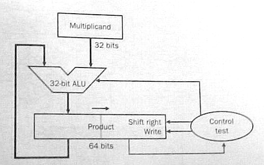
Either scheme performs 32 iterations. Each iteration:
- adds the multiplicand to the product if the rightmost multiplier
bit equals 1;
- shifts the multiplicand to the left (fig. 3.5) or the product to
the right (fig. 3.7) one bit position; and
- shifts the multiplier one bit position to the right to discard the multiplier bit just treated and bring the next bit into the rightmost position.
Multiplying Signed Integers: The multiplicand and the product are in two's complement form so additions and subtractions use two's complement arithmetic.
The multiplier is in two's complement form so its sign bit has a negative weight. Does this complicate the algorithm at all? Not really. If the sign bit of the multiplier is 1 then subtract the multiplicand from the product instead of adding it to the product.
Using Carry Save Adders: The number of iterations is reduced if each iteration examines several multiplier bits and adds several multiples of the multiplicand to the product simultaneously. A tree of carry save adders is used to quickly perform the many additions.
A carry save adder receives three numbers and partially adds them together; instead of producing their sum as one number it produces two numbers which have the same sum. An n-bit carry save adder is a set of n full adders. The full adders are not chained together; each full adder receives three bits, a, b, and c, and produces two bits, r and s, such that 2*r + s = a + b + c. If corresponding bits of three n-bit numbers, A, B, and C, are fed to the set of n full adders the set produces two n-bit numbers, R and S, such that 2*R + S = A + B + C. Number R is shifted left one place to produce a number R' with n+1 bits. R' = 2*R so R' + S = A + B + C. A carry save adder is very fast because it simply outputs the carry bits (as the number R') instead of propagating them to the left.
A carry save adder (CSA) is shown as a block with three inputs and two outputs. Each input and output is a binary number.
   +-----+
-->|     |
   |     |-->
-->| CSA |
   |     |-->
-->|     |
   +-----+
To add K numbers together feed them into a tree of K-2 carry save adders to produce two numbers with the same sum; then add those two numbers together with a carry lookahead adder The delay is not much longer than the carry propagation delay in the carry lookahead adder. Nine numbers are summed in the following diagram:
   +-----+
-->|     |   +-----+
   |     |-->|     |
-->| CSA |   |     |   +-----+
   |     |-->|     |-->|     |
-->|     |   | CSA |   |     |
   +-----+   |     |   |     |   +-----+
             |     |-->|     |-->|     |
   +-----+   |     |   |     |   |     |
-->|     |-->|     |   | CSA |   |     |   +-------+
   |     |   +-----+   |     |   |     |-->|       |
-->| CSA |             |     |-->|     |   | Carry |
   |     |   +-----+   |     |   | CSA |   | Look- |-->
-->|     |-->|     |   |     |   |     |   | ahead |
   +-----+   |     |-->|     |   |     |   | Adder |
             |     |   +-----+   |     |-->|       |
   +-----+   | CSA |             |     |   +-------+
-->|     |   |     |             |     |
   |     |-->|     |------------>|     |
-->| CSA |   |     |             +-----+
   |     |-->|     |
-->|     |   +-----+
   +-----+
The tree diagrammed above can be used to rapidly add eight
multiples of the multiplicand to the product. The product of two
32-bit numbers can be computed in 4 iterations where each iteration
examines 8 bits of the multiplier. A copy of the multiplicand
(shifted appropriately) is fed into the tree for each 1-bit in the
multiplier (zero is fed in for each 0-bit.) The ninth input of the tree
receives the previous product and the tree produces the next product.
The fastest way to multiply is to examine all multiplier bits in parallel and feed all required multiples of the multiplicand into a large carry save adder tree. With today's technology a VLSI chip can easily hold the large number of full adders required by this scheme.
MIPS Multiplication: The product of two 32-bit numbers has 64 bits. Registers only have 32 bits so where is the product placed? Some computers place it in a pair or registers: if the destination specified in the instruction is $4, the product is placed in $4 and $5. MIPS has a different approach: store the product in a special 64-bit register and let the program access the left half, Hi, and/or the right half, Lo, with other instructions. Move from Hi (mfhi) copies the left half to a general register and Move from Lo (mflo) copies the right half. The multiplication instructions specify the sources but not the destination, another example of good design demands compromise.
3.5 - Division
Division is harder than the other three basic arithmetic operations (addition, subtraction, and multiplication.) It's harder to learn in grammar school and it's harder to implement in a computer. The divide instruction is slower than the other three arithmetic instructions in almost every computer.
Division starts with two operands, a dividend and a divisor, and computes two quantities, a quotient and a remainder, such that the remainder is less than the divisor and:
A Decimal Example: Here we use long-division to divide decimal 61927 by decimal 469:
        132
    -------
469 ) 61927
    - 469    <-- 1 * 469
      ---
      1502
    - 1407   <-- 3 * 469
      ----
        957
      - 938  <-- 2 * 469
        ---
         19
The dividend is 61927 and the divisor is 469.
Long-division found a quotient of 132 and a
remainder of 19.
A Binary Example: Long-division with binary numbers is similar. Here we divide 100001010 by 10111:
             1011
      -----------
10111 ) 100001010
       - 10111    <-- first position of divisor
        ------
          101001
       -   10111  <-- divisor shifted right two places
          ------
           100100
       -    10111 <-- divisor shifted right one more place
           ------
             1101
The dividend is 100001010 (decimal 266) and the
divisor is 10111 (decimal 23). Long-division found a
quotient of 1011 (decimal 11) and a remainder
of 1101 (decimal 13).
How was the first position of the divisor determined? We first tried to align the divisor (10111) with the leftmost five bits of the dividend but then the divisor is larger than that part of the dividend (10000). We shifted the divisor right one place so it is less than or equal to dividend bits 100001. This alignment determines where the leftmost 1-bit of the quotient occurs.
Why is the next quotient bit zero? The first subtraction gave us a difference of 1010 and the next dividend bit was appended (brought down) to make it 10100. But 10100 was less than the divisor so the next quotient bit is 0 and another dividend bit was appended to get 101001. Since 101001 is larger than the divisor we now subtract the divisor again.
The second subtraction gives a difference 10010 and the last dividend bit was appended to make it 100100. Since 100100 is larger than the divisor the last quotient bit is 1 and the divisor was subtracted to get a remainder of 1101.
This example illustrated the basic steps a computer performs in a division operation:
- comparing the value of the divisor with the value of the dividend
with certain alignments; and
- shifting the aligned divisor to the right (and entering a 0-bit in
the quotient) whenever it is greater than the dividend; or
else
- subtracting the aligned divisor from the dividend (and entering a 1-bit in the quotient) whenever it is less than or equal to the dividend.
Register Sizes: A 32-bit register holds a natural number in the range of 0 through 232 - 1. If we use 32-bit registers for the divisor, the quotient, and the remainder how many bits should we allow for the dividend? The remainder must be less than the divisor so it is in the range of 0 through 232 - 2. Since:
the dividend is in the range of 0 through 264 - 232 - 1 so it should held in a 64-bit register.
Division Overflow: The divisor is in a 32-bit register but its value can be very small. If a large dividend is divided by a small divisor the quotient may be too large for a 32-bit register so the division overflows.
Given the value of a divisor what's the largest dividend value that can be divided without overflow? The largest quotient is 232 - 1 and (largest remainder) = (divisor) - 1 so (largest dividend) = 232 * (divisor) - 1.
Before dividing, overflow can be checked by shifting the divisor 32 places to the left and comparing its value to the dividend: the dividend value should be less than the value of the divisor with this alignment. No dividend can be negative so this check also discovers divide-by-zero errors.
The Basic Steps in One Iteration: Each iteration compares the dividend to the divisor with a certain alignment. If the dividend is less than the divisor then the next quotient bit is 0 and the dividend is not changed. Otherwise, if the dividend is greater than or equal to the divisor then the next quotient bit is 1 and the aligned divisor is subtracted from the dividend.
There are (at least) three different methods of performing these steps:
- Do the comparison but don't change the dividend until the next
quotient bit is determined. Subtract the aligned divisor from the
dividend only if the next quotient bit is 1.
- Subtract the aligned divisor from the dividend and then check
the sign of the new dividend. If the new dividend is negative then
generate a 0 quotient bit and add the aligned divisor back into the
dividend to restore the original dividend. Otherwise, if
the new dividend is non-negative then generate a 1 quotient bit and
leave the dividend as is (because the subtraction has already been
done.)
- Start the iteration with the aligned divisor already subtracted from the dividend. Check the dividend sign; the next quotient bit equals 0 if the dividend is negative or equals 1 if the dividend is non-negative. Then fix the dividend for the following iteration by adding half the aligned divisor to the dividend if the quotient bit is 0 or subtracting half the aligned divisor from the dividend if the quotient bit is 1.
Method 2 is called restoring division and method 3 is called non restoring division. Very few computers use method 1.
Implementing Restoring-Division: Figure 3.10 in the text shows one scheme for doing restoring-division using a 64-bit ALU. One 64-bit register holds the dividend at the start and the remainder at the end. Another 64-bit register holds the 32-bit divisor: the divisor starts out in the left half of the register and is shifted right one place with each iteration. Another 32-bit register receives the quotient bits as they developed: each iteration shifts the register left one place and enters a quotient bit at the right end.
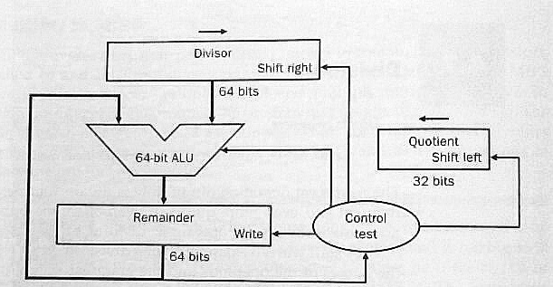
Figure 3.11 shows the flow chart for division using this hardware. Note that the loop is performed 33 times and produces 33 quotient bits! The first iteration is really the overflow check: the first quotient bit equals 1 if and only if division overflows.
Figure 3.13 cuts the size of the ALU and the divisor register to 32 bits. Rather than shift the divisor to the right one place with each iteration the dividend (remainder) is shifted to the left one place.

The 64-bit remainder register in fig. 3.13 is initialized with the dividend but each iteration shifts it left one place. At the end of division the quotient will be found in the right half of the remainder register (and the remainder will be found in the left half.)
Signed Integer Division: Recall the fundamental equation for division:
Dividing +7 by +2 generates a quotient of +3 and a remainder of +1 to satisfy this equation. A quotient of +4 and a remainder of -1 also satisfies this equation but that solution is rejected because most programmers expect to see a non-negative remainder when a positive number is divided by a positive number.
Suppose -7 is divided by +2. One solution to the fundamental equation is a quotient of -3 and a remainder of -1. Another solution is a quotient of -4 and a remainder of +1. Which solution is best? Since (+7)/(+2) gives a quotient of +3 most programmers would expect to see a quotient of -3 for (-7)/(+2).
Now suppose +7 is divided by -2. One solution to the fundamental equation is a quotient of -3 and a remainder of +1. Another solution is a quotient of -4 and a remainder of -1. Again, since (+7)/(+2) gives a quotient of +3 most programmers would expect to see a quotient of -3 for (+7)/(-2).
Finally, suppose -7 is divided by -2. One solution to the fundamental equation is a quotient of +3 and a remainder of -1. Another solution is a quotient of +4 and a remainder of +1. Again, since (+7)/(+2) gives a quotient of +3 most programmers would expect to see a quotient of +3 for (-7)/(-2).
In all four cases the best solution to the fundamental equation generates a non-zero remainder whose sign is the same as the dividend sign. The general rule is:
- Solve the fundamental equation with a zero remainder if possible, otherwise solve the equation with a remainder whose sign is the same as the dividend sign and whose absolute value is less than the absolute value of the divisor.
Some computers don't follow this rule. The real quotient of (699)/(100) is 6.99 so a quotient of 7 (remainder = -1) is more accurate than a quotient of 6 (remainder = +99.) To get the integer quotient closest to the real quotient pick the solution whose remainder has the least absolute value.
A programmer can easily change the machine's rule by adding a bias to the dividend before division and then subtracting the bias from the remainder after division. The bias value usually depends on the divisor. A bias with half the magnitude of the divisor and the same sign as the dividend will change the general rule so the integer quotient closest to the real quotient is selected.
A useful exercise might be to program various cases on your favorite computer to see what quotients signed integer division produces. You may have to program the cases in assembly code because some compilers modify the machine's rule to fit the rule of the source language.
Implementing Signed Integer Division: One way to do signed integer division is: (1) negate the dividend if it is negative; (2) negate the divisor if it is negative; (3) use the unsigned integer division algorithm to get a quotient and a remainder; (4) negate the quotient if the original dividend and divisor had opposite signs; and (5) negate the remainder if the original dividend was negative.
Signed integer division can also be performed using two's complement arithmetic and modifying the unsigned algorithm appropriately. For example, each iteration selects a quotient bit by comparing the dividend sign to the divisor sign.
MIPS Division: Like the multiply instructions, the divide instructions don't specify a destination. The remainder is left in Hi and the quotient is left in Lo.
3.6 - Floating Point
Many numerical operands are not integers; e.g., 1.5, 23.67, 0.0021, pi = 3.141592653589793238..., e = 2.7182818284590... A real number may or may not have an integer value.
Early computers could only handle integers. How was pi stored in ENIAC? The closest integer to pi is 3 but that's a very poor approximation. Since an ENIAC register held ten decimal digits, pi was stored in a register as the closest integer to pi * 109, 3141592654, and the programmer had to remember its scale factor, 109.
A variable, x, with a maximum value of 14.1421 would be stored in an ENIAC register with a scale factor of 108 to give it the maximum precision with no danger of overflow (the maximum register value is 1414210000.)
ENIAC code for y = pi + x would be: a copy of pi's register into y's register; a shift of y's register one digit to the right (since pi's scale factor is ten times the scale factor of x); and an add of x's register to y's register. The maximum value of pi + x is 17.28369265 so the addition can't overflow and the scale factor for y is 108.
Good estimates of the ranges of the real variables were needed so they could be scaled for maximum precision with no danger of overflow. Overflow bugs were common and difficult to fix. To reduce the scale factor of a variable because it overflowed, a programmer would have to change the code in every place that defined that variable or used that variable.
An early example of system software was a package of subroutines to perform floating point arithmetic. Precision was reduced so a scale factor could be stored with the value of each real operand. The add subroutine, for example, examined the scale factors of its source operands to shift their values into alignment before summing and then shifted the sum for maximum precision (normalization.)
Even though they sacrificed precision and speed, floating-point subroutine packages were popular in early computers because they eliminated overflow bugs. Later computers included floating-point hardware to regain speed (precision is still sacrificed.)
In a binary computer, the value of a floating-point number is:
where the sign bit, S, is 0 or 1, the exponent, E, is a signed integer, and the significand, F, is a non-negative real number less than some constant. Other names for F are fraction or mantissa.
It's best if the length of a floating-point number is compatible with the machine word size; the MIPS computer has 32-bit single precision numbers and 64-bit double precision numbers. The format of a floating-point number has three fields to store S, E, and F. A single bit suffices for the sign bit, S. How long are the fields for E and F, respectively?
The length of the field storing the exponent, E, dictates the range of floating-point numbers. To show this, assume the field for E is only five bits long. E ranges from -16 to +15 and the magnitude of a floating-point number is less than 215 = 32768 (if F is less than unity.) Many programs have operands larger than 32768 so overflows will occur frequently; a 5-bit field for E is much too short.
The length of the field storing the significand, F, dictates the precision of floating-point numbers. For example, if the field for F is only ten bits long then F can only be stored with a precision of ten bits which is about three decimal digits. Any user expects a computer to be able to compute numbers with much higher precision so clearly the F field must be much longer than 10 bits.
If the total length of a floating-point number is fixed then each bit added to the field for F comes from the field for E. Should a designer pick a long field for F (for high precision) or a long field for E (to mimimize overflow occurrences)? Before the 80's machine designers made many different choices. Now, almost all computers (including the MIPS computer) follow the IEEE 754 floating-point standard.
MIPS Single Precision Numbers: The significand, F, is less than two and the format of a non-zero normalized MIPS 32-bit single precision number is:
| S | E+127 | F-1 |
|---|---|---|
| 1 bit | 8 bits | <----- 23 bits -----> |
A single precision zero has 0-bits in all 32 places:
| 0 | 00000000 | 00000000000000000000000 |
|---|---|---|
| 1 bit | 8 bits | <----- 23 bits -----> |
The exponent, E, of a non-zero number is in the range of -126 to +127 but a bias of 127 is added to E. The 8-bit exponent field really stores E+127 as a natural number in the range of 1 to 254. Biasing the exponent means that a single precision zero has an exponent of -127.
To preserve precision, every floating-point operation normalizes its results so the significand, F, of any non-zero result is at least unity and less than two. There is always a 1-bit in the leftmost position of F so it doesn't need to be stored allowing a 24-bit significand to be stored in a 23-bit field. The number stored in the significand field of a normalized non-zero number is really F - 1 since the hidden leftmost bit has a weight of unity. The precision is 24 bits (about 7.2 decimal digits.)
What's the largest number that can be stored? The bit sequence for the most positive number is:
| 0 | 11111110 | 11111111111111111111111 |
|---|---|---|
| 1 bit | 8 bits | <----- 23 bits -----> |
Changing the sign bit to 1 gives us the bit sequence for the most negative number. The 8-bit exponent field contains decimal 254 so the exponent, E, equals 127. The 23-bit significand field has 23 1-bits so adding the hidden 1-bit makes F = 2 - 2-23. The most positive number that can be stored is (2 - 2-23) * 2127 or about 3.4 * 1038. The most negative number has the same magnitude. Very few good operands exceed these magnitudes so the most likely cause of an overflow is a programming bug.
One way to treat an overflow is to substitute infinity which has the following bit sequence:
| 0 | 11111111 | 00000000000000000000000 |
|---|---|---|
| 1 bit | 8 bits | <----- 23 bits -----> |
An operand set to infinity has some unknown magnitude greater than about 3.4 * 1038. Another special case is Not a Number or NaN with the bit sequence:
| 0 | 11111111 | not all 0-bits |
|---|---|---|
| 1 bit | 8 bits | <----- 23 bits -----> |
An operand set to NaN has an unknown magnitude which may be any value: large or small. For example: infinity divided by infinity equals NaN.
What's the least positive normalized number that can be stored? The bit sequence is:
| 0 | 00000001 | 00000000000000000000000 |
|---|---|---|
| 1 bit | 8 bits | <----- 23 bits -----> |
The exponent is 1 - 127 = -126 and the significand is 1 so the value is 2-126 or about 1.2 * 10-38. What happens with a positive number with a lesser value? The simplest scheme is to change it to zero. An option in the IEEE standard is to store it as a de-normalized number with an all-zero exponent field and a non-zero significand field. A negative number very close to zero is treated in a similar manner.
MIPS Double Precision Numbers: The significand, F, is less than two and the format of a non-zero normalized MIPS 64-bit double precision number is:
| S | E+1023 | F-1 |
|---|---|---|
| 1 bit | 11 bits | <----- 52 bits -----> |
A double precision zero has 0-bits in all 64 places. The exponent, E, of a non-zero number is in the range of -1022 to +1023 but a bias of 1023 is added to E. The 11-bit exponent field really stores E+1023 as a natural number in the range of 1 to 2046. Biasing the exponent means that a single precision zero has an exponent of -1023.
The significand, F, is at least unity and less than two. The precision of F is 53 bits (almost 16 decimal digits) and it is stored in a 52-bit field by hiding its leftmost bit which is always a 1-bit.
The bit sequence for the most positive number is:
| 0 | 11111111110 | 111 . . . 111 |
|---|---|---|
| 1 bit | 11 bits | <----- 52 bits -----> |
Changing the sign bit to 1 gives us the bit sequence for the most negative number. The 11-bit exponent field contains decimal 2046 so the exponent, E, equals 1023. The significand field has 52 1-bits so adding the hidden 1-bit makes F = 2 - 2-52. The most positive number that can be stored is (2 - 2-52) * 21023 or about 1.8 * 10308. The most negative number has the same magnitude. The least positive normalized number is 2-1022 or about 2.2 * 10-308.
Double precision infinity has the following bit sequence:
| 0 | 11111111111 | 000 . . . 000 |
|---|---|---|
| 1 bit | 11 bits | <----- 52 bits -----> |
An operand set to infinity has some unknown magnitude greater than about 1.8 * 10308. The other special case, NaN, has the bit sequence:
| 0 | 11111111111 | not all 0-bits |
|---|---|---|
| 1 bit | 11 bits | <----- 52 bits -----> |
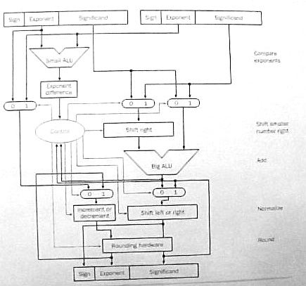
Floating-Point Addition/Subtraction: Subtraction is performed by complementing the sign bit of the subtrahend and adding it to the minuend. Adding two floating-point numbers, A and B, takes four basic steps:
- Alignment: Compare the exponents of A and
B. Let the operand with the greater exponent
be G and the operand with the lesser exponent
be L (the choice is arbitrary if the exponents are equal.)
Subtract the exponent of L from the exponent of G to get the exponent difference, D.
Add the hidden bits to the significands of G and L (a hidden bit is a 1-bit if the operand is normalized.)
Shift the significand of L to the right D bit positions to align it properly with the significand of G.
- Addition: Compare the sign bits of G and
L.
If the sign bits agree then add the aligned significand of L to the significand of G.
If the sign bits disagree then subtract the aligned significand of L from the significand of G. If the difference is negative then negate the difference to make it positive and complement the sign bit of G.
- Normalization: The result is G but it's
significand may be out of range.
If the significand of G is greater than or equal to two then shift the significand one bit position to the right and increment the exponent of G by unity.
If the significand of G is non-zero but less than unity then shift it to the left until it is greater than or equal to unity. Decrement the exponent of G by the number of bit positions the significand is shifted to the left.
If the significand of G equals zero then the result is zero so clear the sign bit and exponent fields of G to zero.
The exponent of G may be out of range after incrementing or decrementing. If the exponent is too large then change G to infinity. If the exponent is too small then change G to zero.
- Rounding: The significand of G may be
longer than the limit (24 bits for single precision or 53 bits for
double precision.) The usual rounding method is truncation: add the
leftmost bit that won't be stored to the bit on its left (the
rightmost bit that will be stored.)
In the worst case, the significand could be rounded up to two. In this case, G must be re-normalized by shifting the significand one bit place to the right and incrementing the exponent by unity. Incrementing the exponent may make it too large so G could be changed to infinity.
Figure 3.17 in the text shows the hardware for floating-point addition/subtraction.
Examples of floating-point arithmetic are much simpler when significand fields are very short. The following examples use the MIPS single precision format with the significand field cut to 7 bits:
| S | E+127 | F-1 |
|---|---|---|
| 1 bit | 8 bits | 7 bits |
- Add B = decimal 15.75 to A = decimal 16.5:
A = 16.5 = (24) * (1 + 1/32) so E = 4 and F = (1 + 1/32). The 8-bit exponent field holds E + 127 = 131 (binary 10000011) and the 7-bit significand field holds F - 1 = 1/32 (binary 0000100) so the bit sequence for A is 0 10000011 0000100.
B = 15.75 = (23) * (1 + 31/32) so E = 3 and the F = (1 + 31/32). The 8-bit exponent field holds E + 127 = 130 (binary 10000010) and the 7-bit significand field holds F - 1 = 31/32 (binary 1111100) so the bit sequence for decimal 15.75 is 0 10000010 1111100.
Alignment: The E field of A is greater than the E field of B so G = A and L = B. The exponent difference, D = 10000011 - 10000010 = 00000001 = decimal 1. The significand of G = 1.0000100 and the significand of L = 1.1111100 after the hidden bits are added in. The significand of L is shifted right one place (0.11111100) because D = 1.
Addition: The sign bits of G and L agree so the two significands are added:
  1.0000100   <-- significand of G
+ 0.11111100  <-- significand of L
 -----------
 10.00000100  <-- sum (new significand of G)
Normalization: The significand of G is greater than two so it is shifted right one place (1.000000100) and the exponent field of G is incremented by unity (10000011 + 1 = 10000100).Rounding: The significand of G = 1.000000100 so it is rounded to 8 places by truncating the rightmost pair of 0-bits. The rounded significand is 1.0000001 since the leftmost bit rounded off was a 0-bit.
Result: The result is G with a sign bit of 0, an exponent field of 10000100 and a significand field of 0000001 (with the hidden bit discarded.) The bit sequence for the result is 0 10000100 0000001.
The result is converted to decimal to see if it's correct. The sign bit is 0. The exponent field is 10000100 = decimal 132 so the exponent is 132 - 127 = 5. The significand field is 0000001 = decimal 1/128 so the significand is 1 + 1/128. The result is (25) * (1 + 1/128) = 32.25 which is the correct sum (16.5 + 15.75).
- Subtract B = decimal 15.75 from A = decimal 16.5:
The operands are the same as the previous example so the bit sequence for A is still 0 10000011 0000100. The sign bit of B is complemented because it's to be subtracted from A; the bit sequence for B is now 1 10000010 1111100.
Alignment: The sign bits are ignored so the alignment step of this example is the same as for the previous example.
Addition: The sign bits of G and L disagree so the significand of L is subtracted from the significand of G:
  1.0000100   <-- significand of G
- 0.11111100  <-- significand of L
 -----------
  0.00001100  <-- difference (new significand of G)
Normalization: The significand of G is less than unity so it is shifted left five places (1.10000000) and the exponent field of G is decremented by five (10000011 - 101 = 01111110).Rounding: The significand of G = 1.10000000 so it is rounded to 8 places by truncating the rightmost 0-bit. The rounded significand is 1.1000000 since the bit rounded off was a 0-bit.
Result: The result is G with a sign bit of 0, an exponent field of 01111110 and a significand field of 1000000 (with the hidden bit discarded.) The bit sequence for the result is 0 01111110 1000000.
The result is converted to decimal to see if it's correct. The sign bit is 0. The exponent field is 01111110 = decimal 126 so the exponent is 126 - 127 = -1. The significand field is 1000000 = decimal 1/2 so the significand is 1 + 1/2. The result is (2-1) * (1 + 1/2) = 0.75 which is the correct difference (16.5 - 15.75).
The following examples are left as exercises. With a short 7-bit significand field the last example has a small round-off error.
- Add decimal -63 to decimal 66.
- Subtract decimal -63 from decimal 66.
- Add decimal 2040 to decimal -2096.
- Subtract decimal 2040 from decimal -2096.
Floating-Point Multiplication: Let A, B, and C be floating-point numbers where C is the product of A and B. The sign bit, exponent field, and significand field of C are determined as follows:
- The sign bit of C is a 0-bit if the sign bits of
A and B agree, otherwise, the sign bit of
C is a 1-bit if the sign bits of A and
B disagree.
- The exponent of C is the sum of the exponents of
A and B. When summing biased exponents the
bias should be subtracted from the sum to get the correct biased
exponent of C.
- The significand of C is the product of the significands
of A and B. The hidden bits should be included
before the significands are multiplied.
- If A and B are normalized non-zero
numbers then their significands must be greater than or equal
to unity and less than two. The product of the
significands must be greater than or equal to unity and
less than four. The product significand may already be
normalized (if its value is less than two) or may require a shift of
one place to the right (if its value is greater than or equal to two.)
Unity should be added to the exponent of C if the
significand is shifted right one place.
- The product of two significands of length N has a length of 2*N so it must be rounded off to N bits. As with floating-point addition/subtraction, rounding may cause re-normalization.
For an example we let A = decimal 16.5 and B = 15.75 and use the same format as the addition/subtraction examples above. The operands are the same as for the first addition/subtraction example so the bit sequence for A is 0 10000011 0000100 and the bit sequence for B is 0 10000010 1111100.
- The sign bits of A and B agree so the sign
bit of their product, C is a 0-bit.
- The exponent field of A is 10000011 = decimal 131
and the exponent field of B is 10000010 = decimal 130.
The exponent field of C is their sum minus the bias of
127; 131 + 130 - 127 = decimal 134 = 10000110.
- With their hidden bits included, the significand of A =
1.0000100 and the significand of B = 1.1111100 so their
product is:
  1.1111100   <-- multiplicand (B's significand)
* 1.0000100   <-- multiplier (A's significand)
  ----------
  0.000011111100
  1.1111100
  --------------
 10.000001111100
- The product is greater than two so it is shifted right one place
and unity is added to the exponent field of C. The
exponent field of C is now 10000111 and the significand
is now 1.0000001111100
- The significand is rounded off by discarding the rightmost six
bits (111100). The leftmost round-off bit is a 1-bit so the
significand is 1.0000010 rounded off to eight places.
The significand field of C = 0000010 after the hidden bit is removed. The bit sequence for C is 0 10000111 0000010.
The product, C, is converted to decimal to check the arithmetic. The exponent field is 10000111 = decimal 135 so the exponent is 135 - 127 = 8 with the bias removed. The significand field is 0000010 so the significand is (1 + 1/64) with the hidden bit included. The value of C = (28) * (1 + 1/64) = 260. The correct product is 16.5 * 15.75 = 259.875 so an error of 0.125 was caused by the round-off.
The following examples are left as exercises. With a short 7-bit significand field all examples have round-off errors.
- Multiply decimal 63 by decimal 66.
- Multiply decimal 2040 by decimal -66.
- Multiply decimal -2040 by decimal -2096.
- Multiply decimal -2040 by decimal 63.
Floating-Point Division: Floating-point division is not discussed in the text. As an exercise try to outline its basic steps.
3.8 - Fallacies and Pitfalls
The text describes the infamous floating-point divide problem in the first Pentium chips. Some of the most significant bits of the divisor and the dividend are fed into a lookup table to guess whether the next two bits of the quotient are -2, -1, 0, +1, or +2. Any error in the guess is corrected on a subsequent pass.
Unfortunately five entries in the lookup table were wrong - the first 11 quotient bits were always correct but bits 12 through 52 might have errors.
Intel discovered the bug in July 1994 but it would take several months to change, reverify, and put the corrected chip into production. They decided that the error was so insignificant that they would just go ahead and produce bad chips until they got a good chip design in January 1995. A big mistake!
In September 1994, Prof. Nicely at Lynchburg College in Virginia discovers the bug, calls Intel technical support, and posts his discovery on the Web when he gets no official reaction.
In November 1994 Electronic Engineering Times puts the story on its front page and other newspapers pick up the story. Intel issued a press release calling the problem a glitch that would affect only a few dozen users. Customers were told to describe their application to Intel and Intel would decide whether or not they needed a new chip without the bug.
In December 1994 IBM stops shipping PC's with the Pentium and Intel finally issues a press release apologizing for the way they handled the problem and offering to replace any bad chip with a good chip for any owner that requests it. It's estimated that this recall cost Intel $300 million.
Apparently, Intel learned a lesson. In April 1997 a bug was found in the Pentium Pro and Pentium II microprocessors but Intel publicly acknowledged the problem and offered a software patch to get around it.
Kenneth E. Batcher - 8/27/2004